Condenser Design Calculation Pdf Reader


Condenser Design Calculation Pdf Reader File
As the properties(kL, ϸL, µL) of the condensate changes with the temperature ,so some modifications are being done to compensate for that . Tf =βTw +(1- β)Tsat Where β-weight factor (recommended in the literature from 0.5 to 0.75) Condensate sub cooling The temp in the condensate film drops from Tsat at the liquid vapour interface to Tw at the wall. Therefore the avg condensate temperature, TL is less than Tsat, and hence the condensate leaving the surface is sub cooled. Accounting for sub cooling, the rate of heat transfer is Q=W ƛ +WCp,L (Tsat - TL)= Whfg*
Cp,L heat capacity of condensate W- condensation rate to account for both sub cooling and inertial effects h/hNu =(1+(0.683 -0.228 PrL-1)Ԑ)^0.25 hNu - heat transfer coeff by basic nusselt theory Ԑ- Cp,L (Tsat - Tw)/ƛ PrL - Cp,L µL/ kL above eqn is valid for Pr>0.6 Q=NhD0L∏(Tsat - Tw) Tw=…………… Then Tf can be obtained by the eqn given above Mass flow rate of water =ϸAu U –flow velocity A of tube can be calculated from the above eqn And the total area= N∏DL And the condensation rate –Q/hfg* Some FACTS to remember
In drop wise condensation Heat transfer coefficient is considerably high as compared to film condensation. The reason being the direct contact of vapor with the cooler surface. The effectiveness of a condenser can be calculated as (1 - eNTU) NTU=(UA/Cmin) Cmin=(mCp)min
References –process heat transfer principles and applications by ROBERT W SERTH Heat and mass transfer –cengel and ghajar
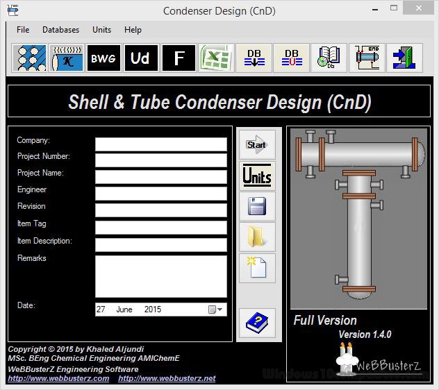
A heat exchanger is a heat transfer device that exchanges heat between two or more process fluids. A heat exchanger is used for transfer of internal thermal energy between two or more fluids available at different temperatures. Sep 04, 2020 Condenser Design. Shell and Tube Condenser Design (CnD) is a software that is made to demonstrate thermal analysis and design calculations required for designing shell and tube condensers. Pml n all songs mp3 download. This software can design, horizontal shell side condensers, horizontal tube side condensers, vertical shell side condensers, vertical tube side condensers. In either design, the condensed vapor forms a film on the cooled surface and drains away to a collection tank for storage, reuse, or disposal. Artistry photo pro: photo edit 3 0 1. In contrast to surface condensers where the coolant does not contact either the vapors or the condensate, contact condensers cool the vapor stream by spraying either a liquid at ambient. Of condenser design Thermohydraulic calculation The thermohydraulic calculation includes all of the parameters which influence the performance of ABB condensers in nor-Large steam condenser of type CM/H. Condensers of this type cover an output range of 150 to 2,000 MW. 1 Two CM/H condenser modules ready for installation on the site of the.

Condenser Design Calculation Pdf Reader 2017
PROCESS DESIGN OF SHELL AND TUBE HEAT EXCHANGER, CONDENSER AND REBOILERS. Calculation of heat transfer co-efficient. Type of heat exchanger and design pressure. Postbox 3.0.5. Downloads lagu opick taubat. The optimum thermal design of a shell and tube heat exchanger involves the. Tube heat exchangers calculations it is very important to remember some. Sandhya namam lyrics in malayalam pdf software. Tower Design Free Online eBook Collection at: www.pdftop.com/ebook/tower+design. Thermal design calculations of Shell & Tube condensers for horizontal condensers, vertical condensers including reflux condensers; main features: +Support S.I.

Condenser Design Calculation Pdf Reader
UNDER MAINTENANCE